All threaded holes in the block and cylinder head should cleaned and tapped with a thread chaser. All bolts being installed should be lubed with a light oil or anti-seize on the bolt threads before assembly.
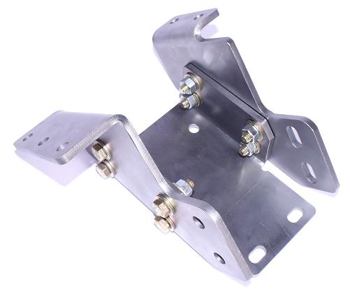
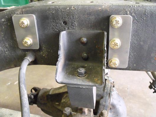
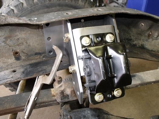
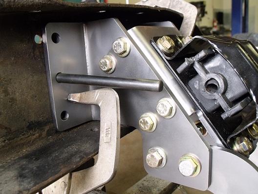
With the original engine removed, remove the original front engine cross member. The original cross member is designed using three pieces. Pull the top pieces first, then the lower cross member. Locate the engine mount pads that are marked "P" and "D". The "P" is the passenger side and the "D" is the drivers side. The picture below is showing the "D" drivers side and the drivers side rear plate. The rear plates have slotted holes on the bottom and two holes that bolt the plate to the frame. The rear sides of the mount pads have slotted holes, the front holes in the mount pads are not slotted. Install 4 3/8 bolts through the rear plate into the mount pad using a washer on both sides and lock nuts. Snug the nuts but do not tighten.
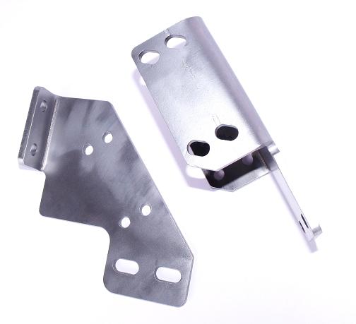
Install the front plates on the mount pads. The lower holes are not slotted, nor are the front holes in the mount pads. This is showing the drivers side assembled. Snug the bolts enough so the plates will still move but do not tighten.
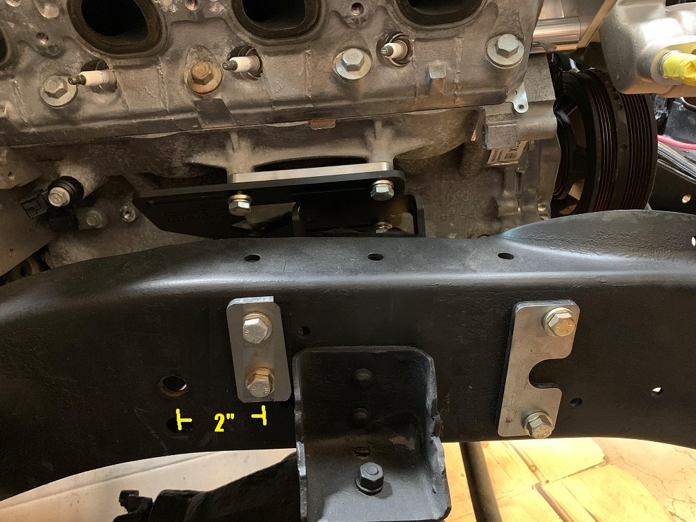
Next, assemble the "P" passenger side in the same manner. The rear plate's four holes are slotted. The rear plate has two bolts that bolt to the frame, the front plate has two bolts that bolt to the frame with a notch in the center. The new updated front plates only have two holes, not three as shown. Some frames have the brake lines mounted on the frame in the front through this center hole. The updated front plate has a notch in the center to clear these applications.
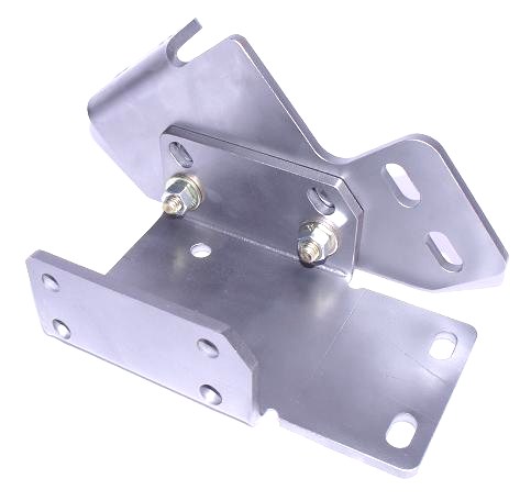
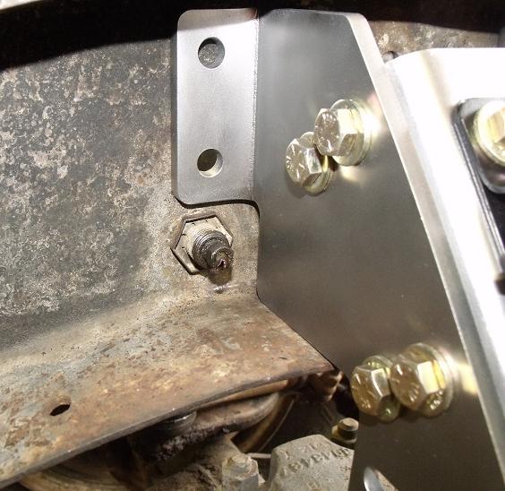
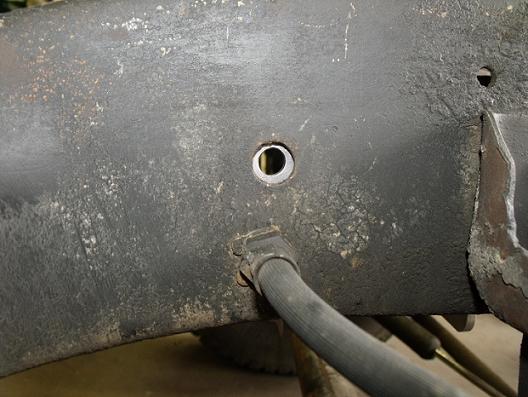
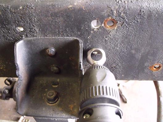
At this point, install your clam shell engine mounts to the frame pads using 3/8 bolts with a washer on both sides and lock nuts. These bolts can be torqued to 28 ft lbs. Place the assembled pieces against the inside of the frame on the corresponding sides. Most factory frames have an existing hole located above where the front brake lines run through the frame. Center the bottom rear hole of the rear bracket on this hole. (If this hole does not exist, you can place the holes in the rear bracket inline with the brake line.)
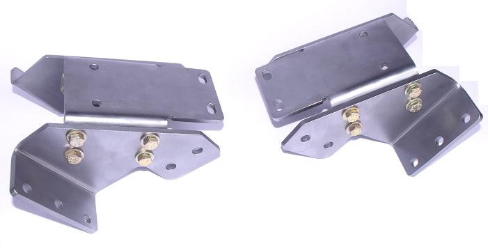
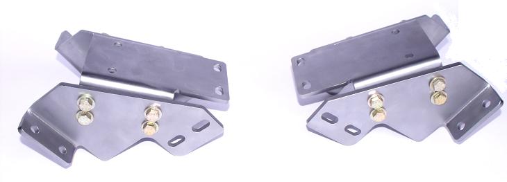
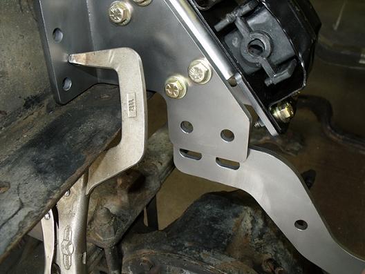
For LS applications you can mount the cross member in two different locations on the frame, towards the firewall or towards the radiator. If you want extra room behind the engine mount it in the forward option, extra room front of the engine mount the cross member in the rearward position.
If you plan on running tall valve covers or LT applications the cross member must be mounted in the forward position. Updated outside forward supports have a notch in the center like the one shown in the forward position.
Passenger side rearward position Passenger side forward position
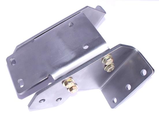
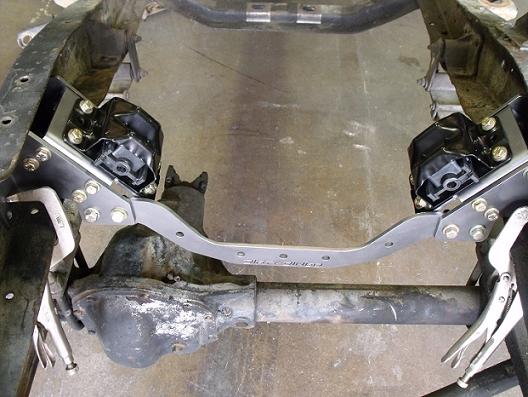
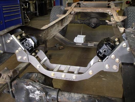
This is showing installation for the rearward position.
Place a temporary clamp on the front bracket clamping it to the frame on both sides. At this point care should be taken to measure from the front sides of the assembly to the front of the frame. Take several measurements to ensure that both sides are sitting evenly from the front of the frame or the front leaf spring perch holes. There are several holes on both sides of the frame that are symmetrical that you can measure.
Next, bolt the lower cross member piece between the frame pad assemblies using 7/16 bolts, a washer on both sides and lock nuts. Snug, do not tighten.
Then install the rear cross member using 7/16 bolts, washers on both sides and lock nuts. Snug, do not tighten.
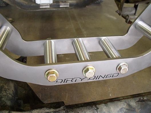
Install the billet spacers with 7/16 bolts, a washer on both sides and lock nuts. These bolts can be tightened. Torque to 45 ft lbs.
With the frame pads and brackets square in the frame, mark the three holes in the front and the two holes in the rear. Remove the center crossmember and remove the mount pad assemblies. Drill holes using a 3/8 drill bit.
Chamfer newly drilled holes to reduce cracking.
Assemble frame pad assemblies back on frame using 3/8 bolts, a washer on both sides, the outer frame plates and lock nuts. Snug, do not tighten.
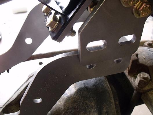
Rearward position
Install center cross member assembly. Snug the four 7/16 bolts on both sides. At this point you can tighten the frame pads to the frame on both sides. Tighten the four front and the four rear bolts on the mount pad assemblies. Next, tighten the four 7/16 bolts on each side of the frame pad assembly to the cross member. At this point all the bolts should be tight. The newly designed side plates have a larger area from the bottom of the bracket to the frame for better clearance of brake and fuel lines. Depending on what model you have the fuel and brake lines may need to be rerouted.
* Gen III/IV engines will require using a Holley 302-1 oil pan and Gen V engines will require using a Holley 302-20 oil pan.
* If you are using tall valve covers or coil covers you will need to mount the cross member in the forward position to clear the firewall.