Use the following information to help out with your GM V8 swap project. Proper installation is the responsibility of the installer. If you have any additional info you have experienced or come across that can help the next person, email us: information@dirtydingo.com
LS GEN III engines typically came with a self-regulating alternator with a 4-Way connector (other than the 04 GTO) while LS GEN IV and LT GEN V engines typically come with an alternator with a 2-Way connector that is expecting a PWM signal from the BCM to tell it what voltage to charge the battery at. GEN III Trucks began to recieve the 2-Way connector expecting the PWM signal in 2005.
In this article I go over how the alternators can be hooked up easily with just two wires to simplify your swap. One to the alternator plug and one to the battery post. The term "1-Wire" carries over from 1-Wire alternators for SBC/BBC GEN 1 setups. The true 1-Wire setups used only a charge wire and grounding points. You can still run a true 1-Wire setup, but charging ONLY begins when they are at the 1200-1400 RPM's and may lead to issues especially when trying to charge at idle. Do not confuse the term "1-Wire" alternator with the simple way to hook up your alternator that I will be going over later in this article. You will see and hear people talk about a 1-Wire plug to use on SBC GEN III, IV, and V swaps, but they still require an outside source to excite the alternator. An "Excite" source is something to tell it to start charging the battery. A true 1-wire setup requires an alternator designed for just the charge wire.
Tech Tip From Powermaster: One wire alternators should NOT be "switched", or isolated from the battery. This causes severe internal spikes in the alternator, which could cause damage. We do not recommend switching alternators on/ off while the engine is running. However, if your application requires this, we can custom build alternators that are safely switchable.
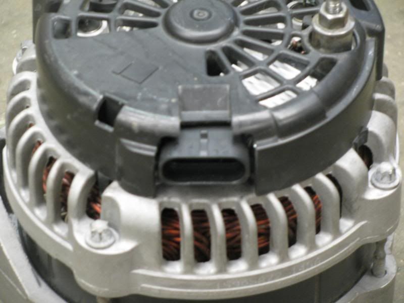
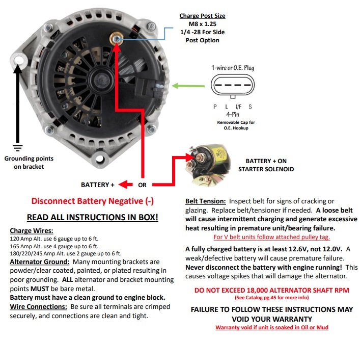
All GM SBC GEN III, IV, and V LS and LT engine alternators have at least a Charge Wire and a Ground Point.
The Charge Wire is connected to the Charge Post on the alternator and the wire goes to either the battery or the positive on the starter. Keep in mind any rules and safety regulations you must follow for what you are building this project vehicle to do. Example wiring diagrams further below on the same page for NHRA guidelines.
The Ground Point comes from the mounting bolts to the alternator going through the bracket. That's why our accessory brackets are NOT painted. If you do paint or powdercoat accessory brackets and/or the alternator, make sure you add a ground to a known good ground point. One of the best ways to get a good ground is bare metal to bare metal. Star washers are your friend here. Use an Ohmmeter to check the resistance to verify a good ground. Below five ohms is an okay ground but the closer to zero the better.
Alternator Install Instructions from Powermaster

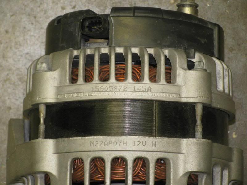
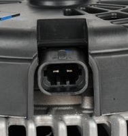
4-Way Metri-Pack Alternators
98-02 Camaro CS130 (5.46")
97-11 Corvette (6.06")
99-2005 Truck AD230 (small case) and AD244 (large case) [5.46"]
GEN III LS engines come from the factory with a self-regulating alternator that uses an external excite source. An excite source is what is telling the alternator to start charging the battery. These alternators typically only need the Indicator Lamp (L) wire ?with a resistor hooked up to an ignition source as well as the Charge Wire and the Ground Point. If you do not use the resistor, you will burn up the voltage regulator on your alternator.
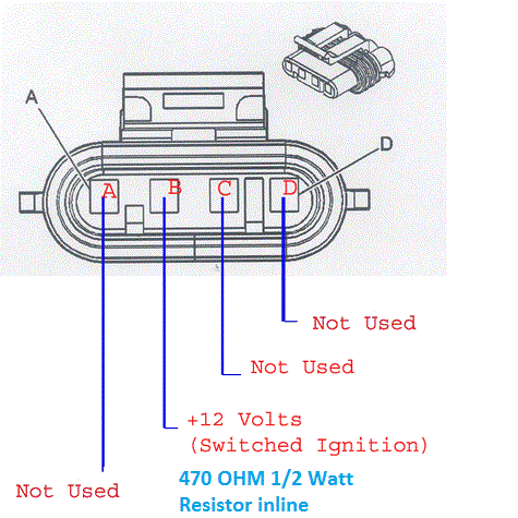
Looking into the 4-Way Metripack plug on the harness
What the letters stand for:
A: P- Phase/Stator: Drives external device such as an electric tach or hour meter
B: L- Lamp/Regulator: Alternator warning lamp to an ignition 12v+ to excite the alternator
C: I- Ignition: Switched ignition 12v+ to excite the alternator
D: S- Sense: Sense the voltage to be controlled
**C usually also has an F next to the I on the same plug. F- Field Monitor: Used to externally monitor the rotor's magnetic field. These regulators are not typically setup for this application.
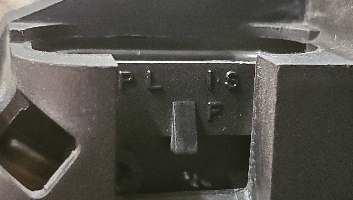
Looking at the alternator 4-Way Connector
How to wire wire them:
A: P- Isn't normally used. Can run a digital tachometer with a Dakota Digital SGI-100BT.
B: L- 12v ignition with a resistor with the option of adding a bulb(LAMP). If you only have an incandescent bulb and it burns out then there will be no current flow!
C: I/F- 12v ignition used when there is no alternator warning lamp in the vehicle or as a redundant method of exciting the alternator
D: S- Battery Positive Voltage can be a fused (5 Amp) link the positive battery terminal, to starter positive, or a main power distribution point to sense the voltage to be controlled however NEVER jumpered directly to the Battery Postive on the back of the alternator. It needs to sense the current draw on the battery, not the output of the alternator. Hooking the Sense wire to the battery positive on the alternator will make the regulator prematurely limit the voltage output.
One thing you may notice here is that the L wire needs a resistor and the I/F does not. The resistor is replicating the resistance you would get from the incandescent bulb in the alternator warning Lamp. Running straight 12V to the L wire will damage the regulator as it was designed with the warning Lamp, not the direct 12V. Some people still put a resistor on I/F anyways. Some people jumper the I/F wire behind the resistor on the L wire, but that defeats the purpose of having a redundant excite source.
Not all regulators are the same! Some regulators are setup for the excite source to be on I/F only instead of the more common L setup. You may have your project wired for one alternator to be excited from L and years down the road you determine the alternator is going out so you put the same alternator back in from the parts store but it doesn't charge. Try depinning the 4-Way Metripack plug and running another excite wire to the other pin and see if that fixes it.
If you do not wire the S wire to Sense the load then the alternator will run in a default output mode. Some cases this is just fine but when you start adding a bunch of accessories that require a lot of power then you are going to start having problems. Eventually your battery will no longer at 14V as the alternator is not keeping up and using its true charging potential. If you wire the Sense wire directly to the battery positive on the back of the alternator, it will prematurely begin limiting voltage. When the Sense wire is hooked up to the battery positive on the alternator, you are sensing the voltage before it drops. You want the Sense wire to go to the battery positive so the regulator will amp up the voltage to keep your battery fully charged. The battery will become fully charged over time with the Sense wire connected to the back of the alternator battery positive post, but in high-performance applications where you have systems such as a fuel pump that is demanding higher voltage such as then time is of the essence. You don't want your project vehicle to fall flat on its face in the middle of an event!
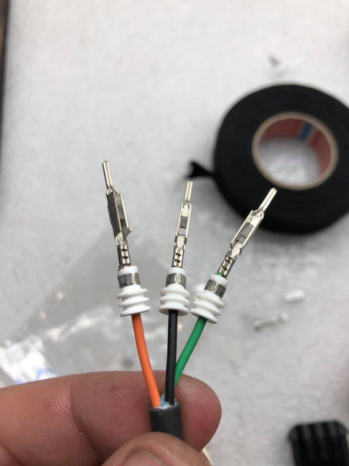
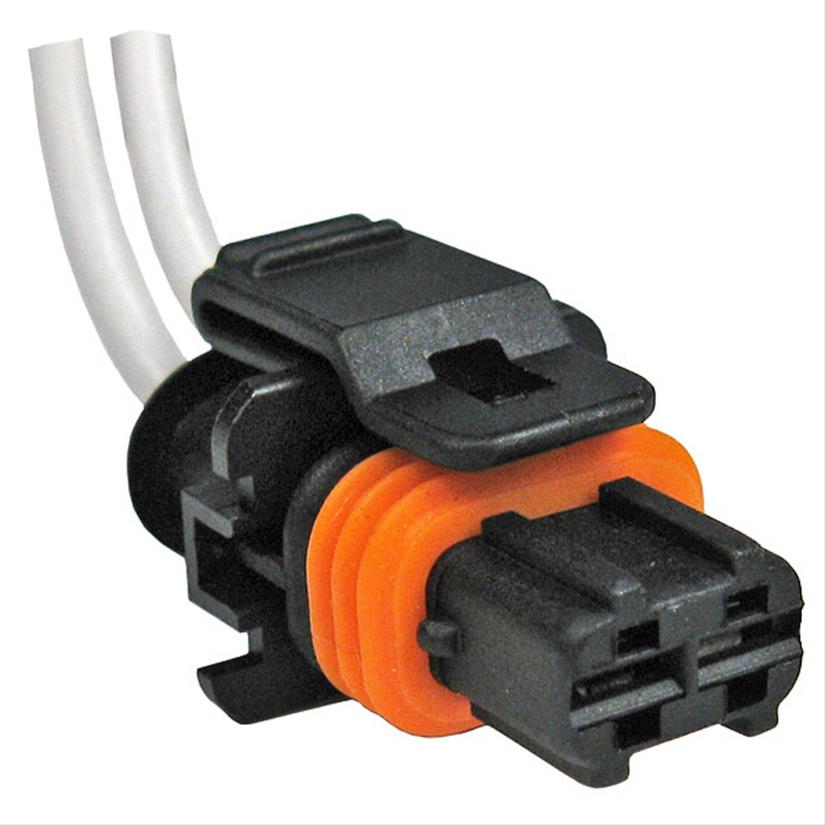
If you need a new Metri-Pack 4-Way connecter, the GM part number is 12186568. That is just the plug with no wires however. Not to be confused with Weather-Pack as those have different terminals and require different crimpers. You could go to the junkyard and get the pigtail from any GEN III LS vehicle other than an 04 GTO. Some times you might need to add or remove certain terminals depending on your application. Use the following information to make the correct alternator connector for your project.
Here are some examples of quality plugs that includes terminals and seals:
Delphi Metri-Pack 150 Series 4-Way Sealed Connector w/ 18-16 AWG
Don't forget to install the correct seal onto the wire before stripping insulation and crimping the terminals. You want to strip exactly 3/16ths of an inch of insulation off put it in the terminal.
Some people just use a filed down paper clip or bobby pin to remove the pins.
Proper removal tool:
Delphi Metri-Pack Terminal Removal Tool 150 Series
Proper Metri-Pack crimping tool is ratcheting as it ensures the full amount of pressure is used every time:
Holley EFI Metri-Pack Crimping tool 20-14 AWG
The part numbers for the correct female terminals can be cross referenced with Metri-Pack's website under "Sealed 150". Here are some direct links:
25 Pack 12048074 18-16 AWG Female Sealed Terminal Metri-Pack 150 Series
50 Pack 12048074 18-16 AWG Female Sealed Terminal Metri-Pack 150 Series
Example photo to show the proper way to install the seals before placing into connector. This is Matt Happel from Sloppy Mechanics. You crimp the stripped wire to the terminal and crimp the big open end of the terminal to the silicone insulation. Key points to success here is the stripped wire doesnt go beyond the crimp and there is no bare wire under the silicone insulation.
If you're not interested in making the wire yourself and just want to keep it simple, then the only 4-Way "1-Wire" alternator pigtail on the market that is ready to go with a resistor already in it, is from Holley. Often you will here this setup referred to as a "1-Wire" setup, however a true 1-Wire alternator is self exciting and doesn't require this excite source wire. If you buy ANY other plug, you will need to add a 470 OHM 1/2 Watt resistor to the L wire. Some GM vehicles have the alternator check light bulb from the factory. The resistor should be wired in parallel with the bulb just in case the bulb burns out so it the alternator still charges.
The 2004 GTO (LS1 GEN III) has a 2-Way plug for the "Mitsubishi Style" alternator
2004 GTO
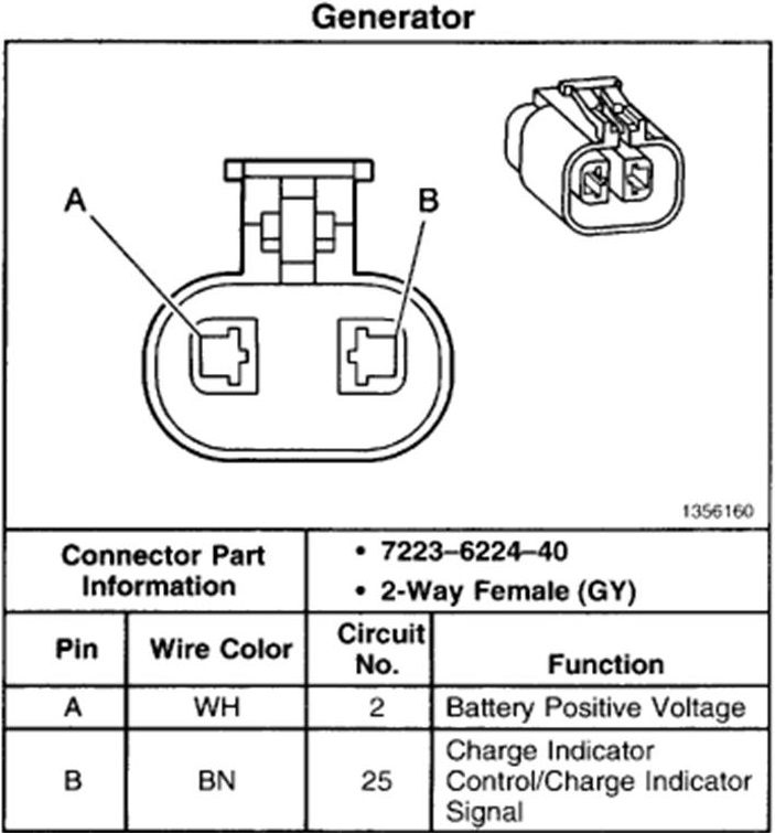
A- S- Sense/Sensor
B- L- Lamp
Same concept from above for the 2004 GTO alternators. Different plug, but there is still the same S and L wires that do the same exact thing.
A "7223-6224-40" connector is a female YAZAKI 58 Connectors X type with 2 poles. I may have organized the name of that connector wrong, but thats all the key words you need. It is a Japanese connector for the "Mitsubishi Style" alternator. You can find the exact part numbers for the plug and the terminals on YAZAKI's Catalog. They make the plug in several different colors, just make sure you are getting the "2 pole" female plug.
New pigtail to save time can be purchased from EFI Connection
Helpful Links:
LS1 Thee Alternator FAQ Sticky Thread
-Multiple LS alternator wiring diagrams from stock applications
Billa Vista Tech Article - Alternator Bible
-In-depth Alternator Tech Article
-Goes over how to properly setup an alternator warning lamp
LS1Tech Article about the 05+ Generator Battery Control Module
Delco Remy Sense wire article
_______________________________________________
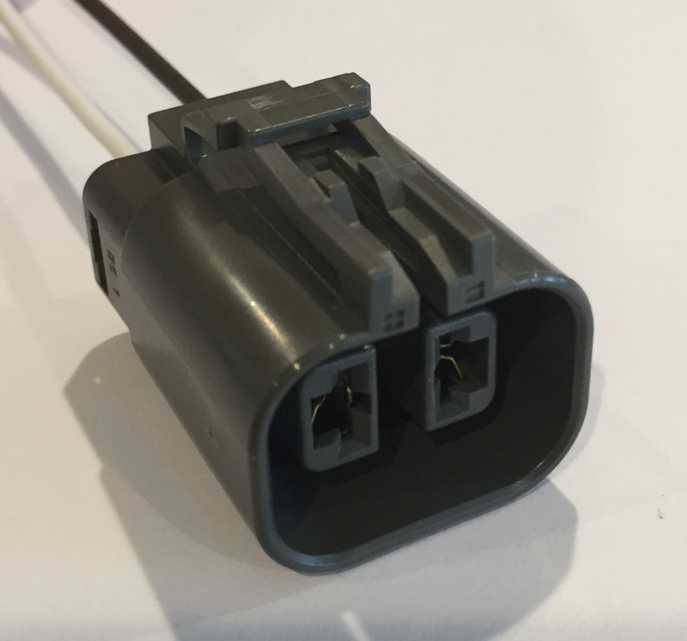
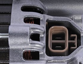
2-Way Connector External Regulating Alternators
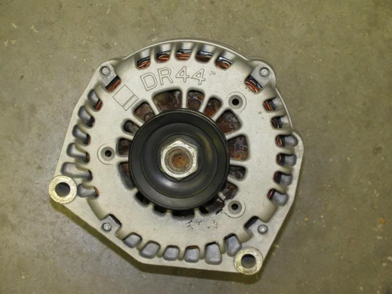
DR37 (small case from trucks), DR44 (large case from trucks)
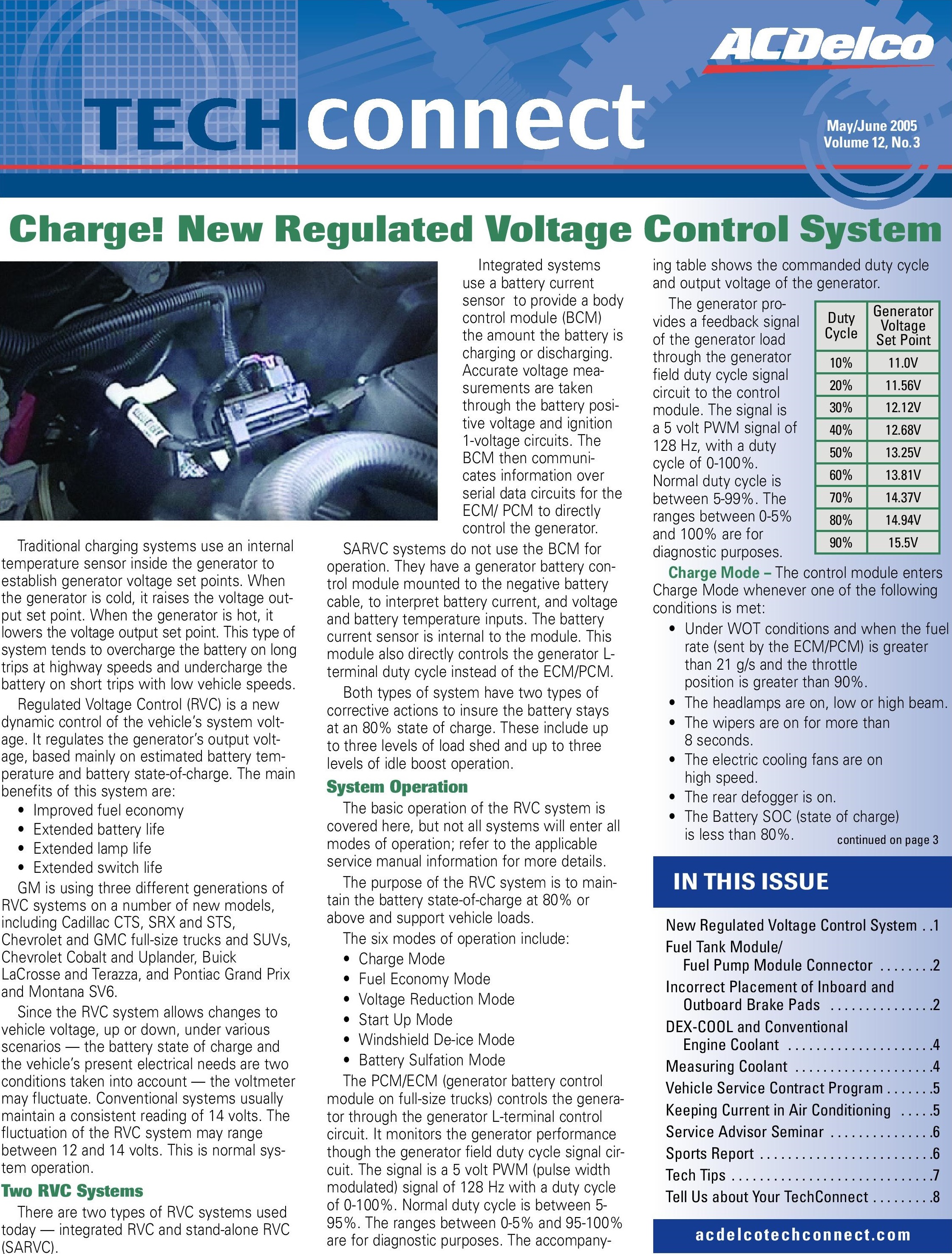
GEN IV LS and GEN V LT engines come from the factory with an externally regulated alternator. These alternators are looking for a Pulse Width Modulation (PWM) signal from the Engine Control Module (ECM)/Body Control Module (BCM) to tell it what voltage to put out to charge the battery. Without using an external regulator, the alternator will default to a 13.8V limp mode which is only a 60% duty cycle! This may work in some light duty applications but if you want the alternator to charge the battery to its full potential, you will need an external regulator. A 90% duty cycle charges at 15.5V!
If you are not running the stock ECM/BCM, then you can either change the regulator in the alternator itself or run an aftermarket external regulator setup. When it comes to a high-performance build or a quality swap, it helps to understand how the GM SBC GEN IV/V alternators work.
**Note that these 2-Way connector alternators are not able to be wired to a warning lamp. If you want to retain the factory warning lamp, then convert the regulator or change the alternator.
Interchangeable part numbers for a new 2 wire plug: GM 89046837, GM 13585849, GM 12186308, Pico 5671A, ACDelco PT2057, ACDelco PT2971, ACDelco PT2787, Standard Motor Products S1437
ACDelco PT2971
Michigan Motorsports Pigtail

Here is an ACDelco Technical Training article that I have archived. It helps to open it in a new tab on your browser so the words are bigger and easier to read.
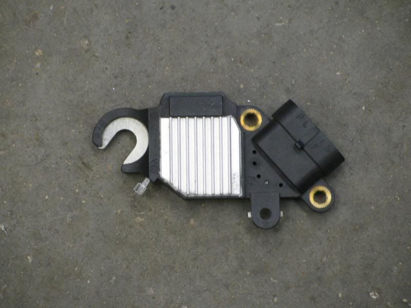
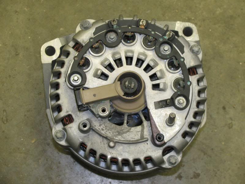
Changing the Regulator
Changing the regulator in the alternator will also change the plug to the GEN III Metri-Pack 4-Way connector. It is not just a simple plug and play solution as it involves soldering and cutting the plastic cooling duct on the rear to allow the larger 4-Way connector to fit. This method is much cheaper than buying a new alternator with the 4-Way plug on it already.
Here is an excerpt from a popular trifive.com article:
As far as I know, all Gen IV alternators have internal regulators that are controlled by a PWM (Pulse Width Modulation) signal from the ECM. They also rely on GBCM (Generator Battery Control Module) and BCM (Body Control Module) input to function correctly. Without the BCM and GBCM, the alternator will default to 100% duty cycle which is 13.8 volts at all times regardless of electrical load or battery discharge level. Also, the ECM will throw DTCs (Diagnostic Trouble Codes) if it doesn't recieve the input form the BCM. Even if one were to wire in the additional modules, there is no wire that will activate the "idiot" light in a stock tri-five dash.
In all cases where your swap doesn't have a BCM and GBCM, the ECM will require programming to remove the alternator related DTCs. They are P0621 and P0622.
...
Option 3: Swap a 4-pin regulator into the Gen IV alternator that you already have. This is probably the cheapest option if you don't mind a little fabrication work. This is the option that I chose and I took pictures along the way.
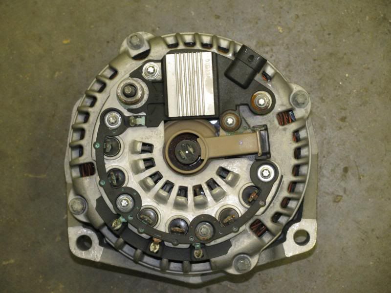
First, what kind of alternator are we talking about? It's the D[R]44 style and easy to identify because it's cast right into the front of the case.
You can see the amperage rating right near the center of the case. Also, note the two pin regulator plug.
You'll want a 4 pin regulator for an AD244 alternator. ... Here's what they look like.
Start the process by removing the plastic cover on the back of the alternator. There are 3 slots where you can use a pocket screwdriver to gently pry off the cover. Once you get it off, you have this:
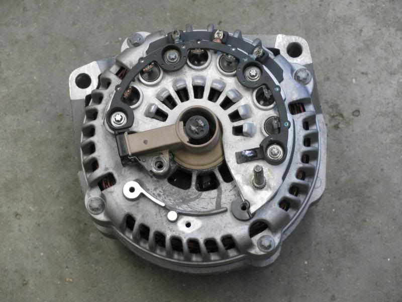
Remove the three screws holding down the regulator. They are E5 reverse Torx, but I used a 4mm 6 point socket. They're not very tight as they're small bolts. You'll also need to remove the sleeve pressed onto the B+ post. The post is knurled like a lug stud. You can gently tap the sleeve side to side with a hammer and it'll loosen up enough to pry up with a flat blade screwdriver. Lastly, you have to unsolder the "P" connector near the B+ post and the regulator can be removed. Then you're left with this:
Now that you have the regulator loose, you can see that most of the mounting holes line up, but the regulators are shaped a little differently. The alternator case will require some modifcations to get it to fit. Note the pie-shaped area that I shaded black in the picture above (at about 5 o'clock in the picture). I used a dremel with a cut off wheel to cut that section of the plate off. It's aluminum and cuts easy. Then you can lay the new regulator in to see the other two mods that are needed. The nub for the bolt just of the left of the regulator plug is a touch too tall and will have to be cut off. Again I used the dremel. Lastly, the 4 pin regulator has a bolt hole just to the right of the plug that wasn't on the old regulator. I drilled a hole in the case with a #29 bit and tapped for a #8-32 machine screw since I didn't have a 4mm x 1 tap. You'll also need a spacer between the regulator and this new hole. The piece that I cut off the screw on the left fit after being filed down slightly. This is all much easier than it sounds as the case is soft aluminum. Just go slow and sneak up on the final product with a file. It took me about an hour to do the case mods.
Now, we have this. Note the pie shaped piece that was removed, the ground nub, and the new tapped hole.
Now, screw down the 4 pin regulator with the original bolts plus a #8-32 x 3/4" screw in the new hole. Lastly, bend the "P" terminal on the new regulator and the "P" terminal from the alternator case together as best you can and solder them together. I actually used a short jumper of 14 gauge wire to help make a mechanical connection prior to soldering. It should look this.
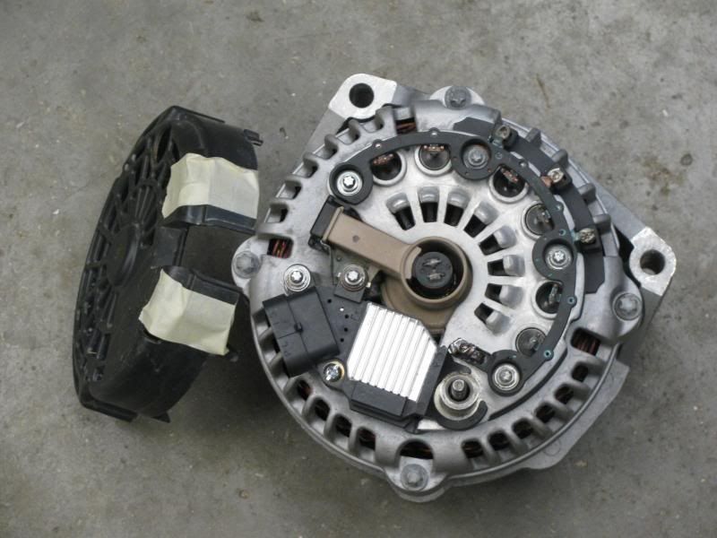
Note the tape on the black plastic dust cover. It is marking the area that needs to be trimmed to fit around the larger 4-pin plug. I used a razor blade to make the initial cuts and finished up with a fine file. When you finish up the trimming, snap it back in place and it looks like this.
At this point I took the alternator to Advance and asked them to test it. Just tell them it is a 2004 Silverado alternator. It passed with flying colors.
The terminal letters are marked right on the regulator plug. When wiring up the "hybrid" alternator, the "L" terminal goes to the factory generator light in the dash and the "I/F" terminal goes to a switched 12 volt source.
Now my generator light works and the alternator maintains 14.7 volts under all loads. I hope this helps with someone else's Gen IV swap.
Running an External Regulator Setup:
If you are going with an aftermarket engine management system or you just dont have the BCM to send the PWM signals, then check out this helpful LS1Tech article:
Here's the secret why GM puts it in later model cars. The computer can command the alternator to put out any voltage from 11V to 15.5V.
Before the late model engine is started, and also after its shut off, GM can check the condition of your battery. Then they can decide how to charge it and they command the alternator to put out the voltage needed to maintain the battery. Also, the alternator tells the computer if it's having trouble putting out the voltage that the computer commanded. To help the alternator, the computer might raise the idle speed for example.
The L pin is the command voltage pin. A 5V PWM signal is sent from the ECM/BCM at a frequency of 128hz. If the duty cycle is less than 10% or more than 90% or just plain not connected, the alternator will go into default mode and put out about 13.7 volts. Enough to keep your car running, but not enough to charge the battery well. Here are the voltages and duty cycles:
|
Duty Cycle |
Voltage |
|
10% |
11.0V |
|
20% |
11.56V |
|
30% |
12.12V |
|
40% |
12.68V |
|
50% |
13.25V |
|
60% |
13.81V |
|
70% |
14.37V |
|
80% |
14.94V |
|
90% |
15.5V |
The F terminal is also a PWM signal. But it's put out by the alternator and read by the computer. The lower the duty cycle the easier the alternator is working. If you want to use the alternator and aren't connected to the correct ECM/BCM then you don't need to connect the F terminal.
So lets say you have one of these 2 pin alternators any you want to use it with an older PCM... Ebay to the rescue.
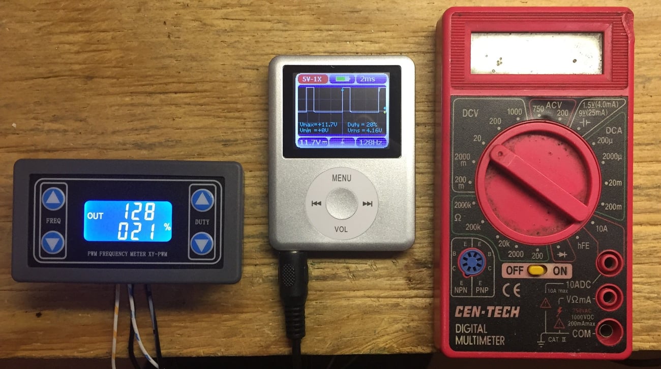
Ignore the two things on the right that are there for size purposes.
The gizmo on the left is a PWM generator that sells for about $4-$5.
It remembers the last setting even after it's turned off so once you set it, that's where it will stay. Set the frequency to 128 and then set the duty cycle to whatever voltage you want the alternator to put out. Let's say you're at the track and you want a little more voltage for you fuel pump and coils. Easy. Just raise the duty cycle. Or you left the lights on and your battery is low.... Easy.
Here's how you wire it:

[Replaced photo from article for a better view of the connector]
Pins from left to right: F, L
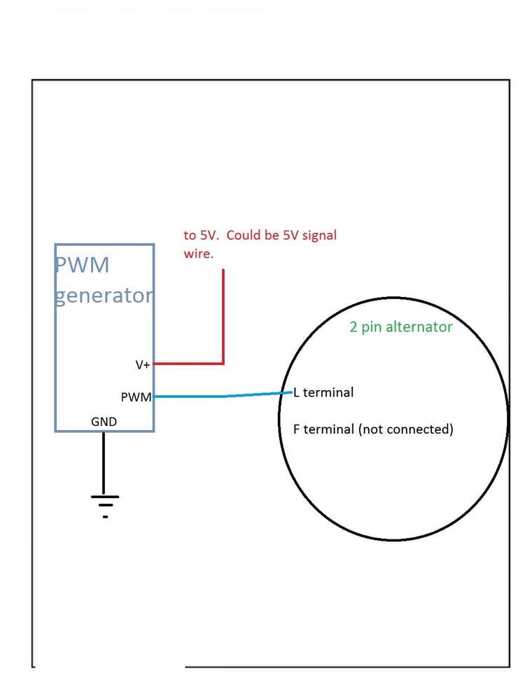
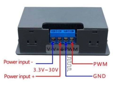
Ignore the Power input -. Apply 5V to the Power input + terminal. You can probably use the 5V signal from the ECM. The PWM controller takes very little power. Connect the ground to signal ground and connect the PWM out to the L terminal of the alternator.
Now go pull that 2 pin alternator out of the trash bin.
One of the most common safety regulations that are followed are from the NHRA.
NHRA General Regulations;
8:1 Batteries (Page 345)
All batteries must be securely mounted; must be of sufficients capacity to start vehicle at any time. Batteries may not be relocated into the driver or passenger compartments. Rear firewall of .024-inch steel or .032-inch aluminum (including package tray) required when battery is relocated in trunk. In lieu of rear firewall, battery may be located in a sealed .024-inch steel, .032-inch aluminum , or NHRA-accepted poly box. If sealed box is used in lieu of rear firewall, box may not be used to secure battery and must be vented outside of body. Relocated battery(s) must be fastened to frame or frame structure with a minimum wiht a minum of two 3/8-inch-diameter bolts. OEM located batteries without complete OEM hold0down hardware must be secured to OEM battery box/tray using the same 3/8-inch-diameter bolt hold-down method described in previous sentence. ("J" hooks prohibited or must have open end welded shut.) Metal battery hold-down straps mandatory. Strapping tape prohibited. A maximum of two automobile batteries, or 150 pounds combined maximum weight (unless otherwise specificed in Class Requirements), is permitted. Maximums may vary according to Class Requirements.
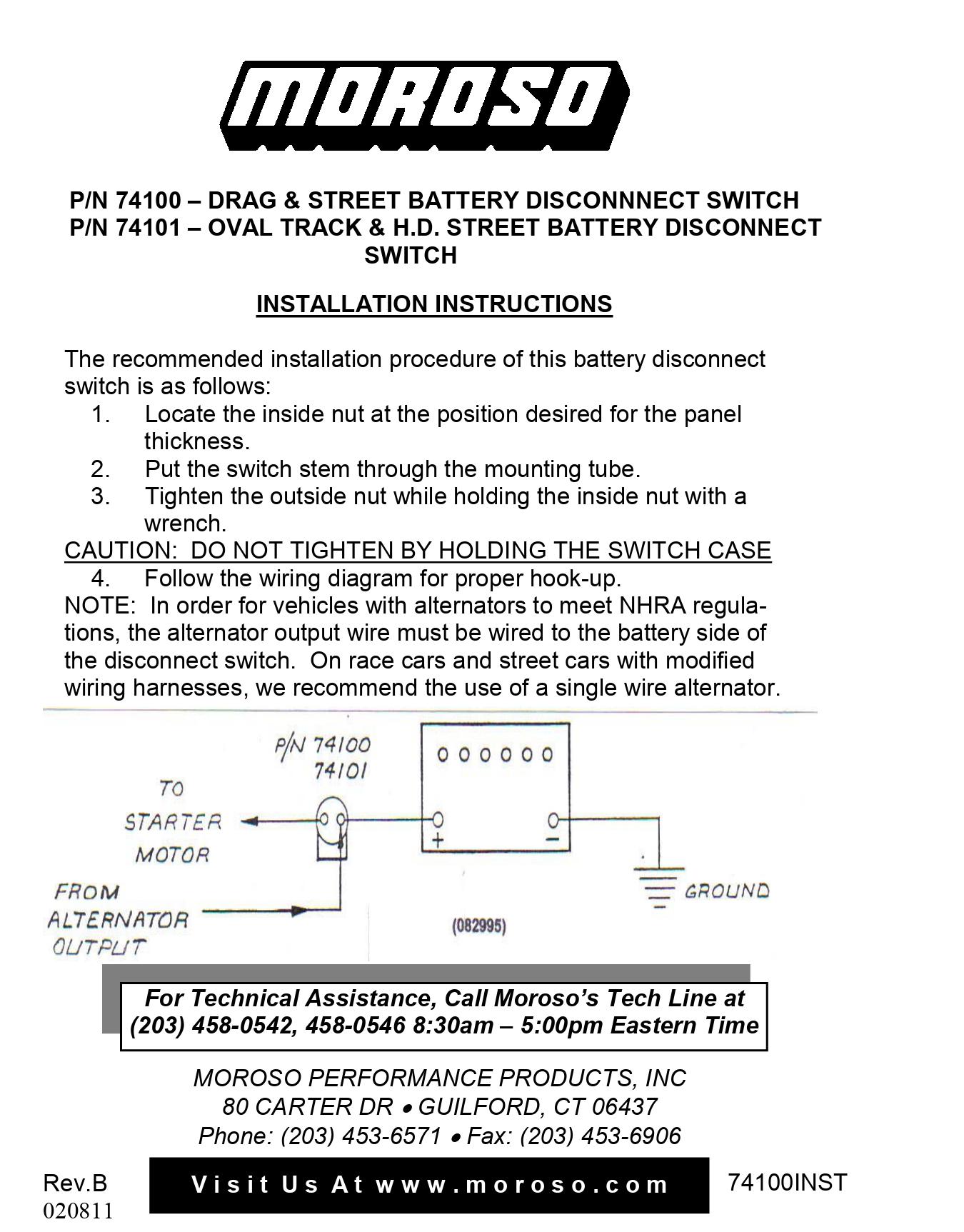
8:4 Master Cutoff (Page 347)
Mandatory when battery is relocated, or as outlined in Class Requirements. An electrical power cutoff switch (one only) must be installed on the rearmost part of each vehicle and be easily accessible from outside the car body. This cutoff switch must be connected to the postive side of the elecrical system and must stop all electrical functions including magneto ignition. The off position must be clearly indicated with the word "OFF". If switch is "push/pull" type, "push" must be the action for shutting off the electrical system, "pull" to turn it on. Any rods or cables used to activate the switch must be minumum 1/8-inch diameter. Plastic or keyed switched prohibited. Switches and/or controls must be located behind rear wheels on rear-engine dragsters.
Moroso makes quality Master Cutoff switches. Take a look at their install instructions for one of their two post cutoff switches:
Now take a look at one of their install instructions for a four post cutoff switch:
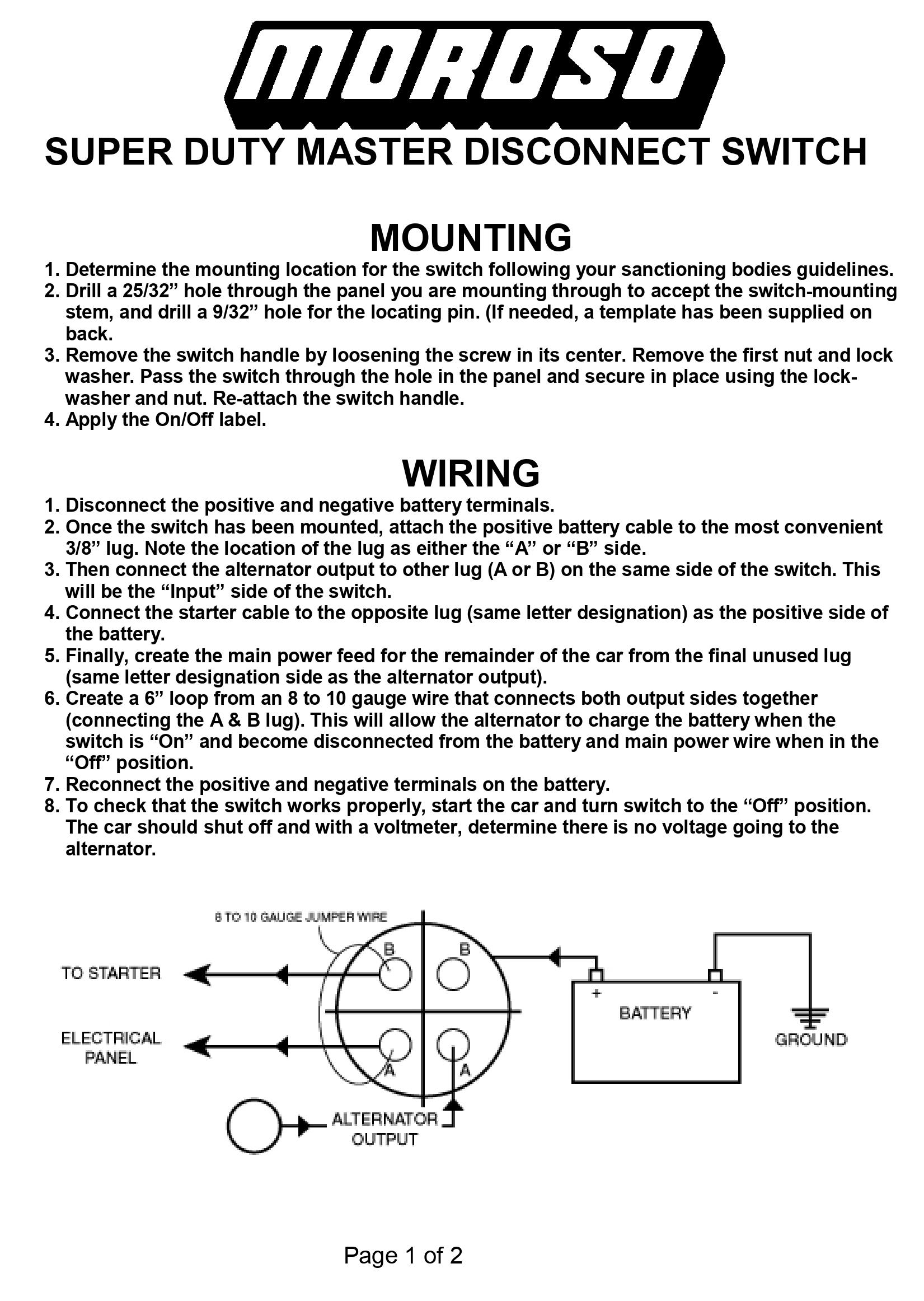
If you do not wire these correctly, you will not pass tech at your local drag strip if they require a cutoff switch for your class. It is very important to have the Battery Postive and the alternator Charge Wire on the same side. If you put the alternator Charge Wire on the other side then the belt driven alternator may backfeed and cause your engine to run for a little bit longer after the cuttoff switch has been applied. In the event that something happens and the cutoff switch needs to be used, time is of the essence. There is a reason these safety regulations are in place. One big reason being it helps prevent an electric fuel pump to stop pumping fuel everywhere and causing a fire.